| Section I | Latest Design RHODES Piano | |
| Chapter 1 | The RHODES Tone Source | 1-1 |
| Chapter 2 | The RHODES Modular Action | 2-1 |
| Damper Release Bar | 2-1 | |
| Damper Push Rod Assembly | 2-2 | |
| Damper Module | 2-2 | |
| Action Rail | 2-3 | |
| Harp Supports | 2-3 | |
| Multiple Hammer Flange | 2-4 | |
| Chapter 3 | Instructions For Disassembly | 3-1 |
| Harp Cover Removal | 3-1 | |
| Nameboard Assembly Removal | 3-1 | |
| Harp Assembly Removal | 3-1 | |
| Damper Release Bar Removal | 3-1 | |
| Damper Module Removal | 3-2 | |
| Hammer Removal | 3-3 | |
| Removal of Keyboard Assembly from Cabinet | 3-3 | |
| Stage Piano | 3-3 | |
| Suitcase Piano | 3-4 | |
| Action Rail and Harp Removal | 3-4 | |
| Harp Support Removal | 3-5 | |
| Cheekblock Removal | 3-5 | |
| Key Removal | 3-5 | |
| Chapter 4 | Dimensional Standards and Adjustments | 4-1 |
| Key Dip | 4-1 | |
| Escapement | 4-1 | |
| Damper Clearance | 4-3 | |
| Damper Module Adjustment | 4-4 | |
| Tension | 4-4 | |
| Alignment | 4-4 | |
| Striking Line | 4-5 | |
| Re-Establishing Striking Line | 4-6 | |
| Timbre Adjustment | 4-7 | |
| Volume Adjustment | 4-7 | |
| Chapter 5 | Tuning The RHODES Piano | 5-1 |
| Electronic Tuning | 5-2 | |
| Stretch Tuning | 5-3 | |
| How to Follow The Chart | 5-5 | |
| Chapter 6 | Repair Procedures and Techniques | 6-1 |
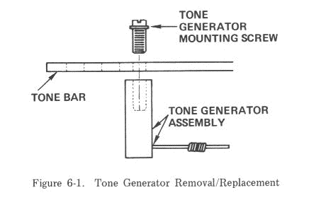
| Tone Generator Assembly Replacement Procedure | 6-1 | |
| Key Pedestal Modification Procedure | 6-4 | |
| Worn Key Bushing Repair Procedure | 6-7 | |
| Key Cap Replacement Procedure | 6-8 | |
| Full-Skirt Type Key Cap | 6-9 | |
| One- And Two-Piece Type Key Cap | 6-9 | |
| Section II | Early Design RHODES Piano | |
| Chapter 7 | Early Design RHODES Piano - Tone Source (Prior to July 1975) | 7-1 |
| The Tine | 7-2 | |
| Chapter 8 | Early Design RHODES Pianos - Action (Prior to September 1975) | 8-1 |
| The Action | 8-1 | |
| Chapter 9 | Early Design RHODES Pianos - Maintenance and Rejuvenation | 9-1 |
| Chapter 10 | Early Design RHODES Pianos - Dimensional Standards and Adjustments | 10-1 |
| Key Dip | 10-1 | |
| Damper Control | 10-2 | |
| Escapement | 10-2 | |
| Signal Strength | 10-4 | |
| Section III | Electrical and Electronic Service Aids | |
| Chapter 11 | Diagrams, Schematics and Pictorials | 11-1 |
| Figure Number |
Title | Page Number |
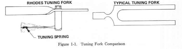
| 1-1 | Tuning Fork Comparison | 1-1 |
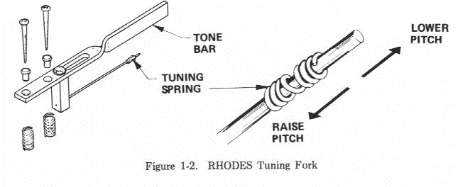
| 1-2 | RHODES Tuning Fork | 1-1 |
| 2-1 | RHODES Modular Action - Single Key View | 2-1 |
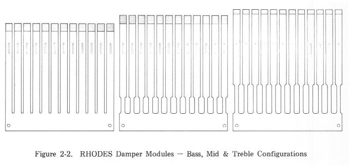
| 2-2 | RHODES Damper Modules - Bass, Mid and Treble Configurations | 2-3 |
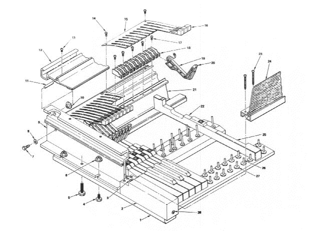
| 2-3 | RHODES Modular Action - Exploded View | 2-4 |
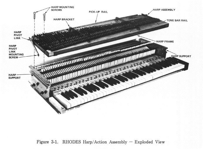
| 3-1 | RHODES Harp/Action Assembly - Exploded View | 3-2 |
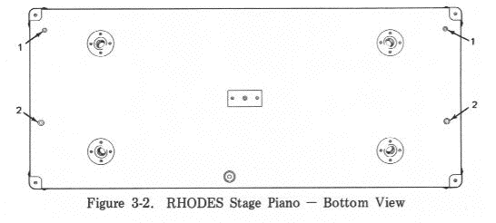
| 3-2 | RHODES Stage Piano - Bottom View | 3-3 |
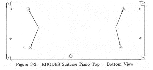
| 3-3 | RHODES Suitcase Piano Top - Bottom View | 3-4 |
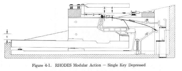
| 4-1 | RHODES Modular Action - Single Key Depressed | 4-1 |
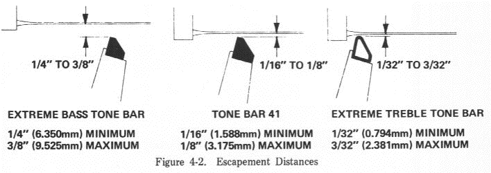
| 4-2 | Escapement Distances | 4-1 |
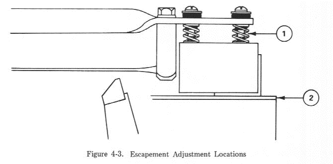
| 4-3 | Escapement Adjustment Locations | 4-2 |
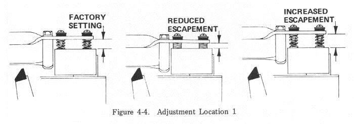
| 4-4 | Adjustment Location 1 | 4-3 |
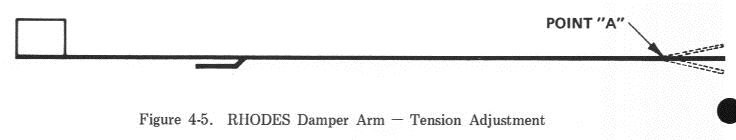
| 4-5 | RHODES Damper Arm - Tension Adjustment | 4-4 |
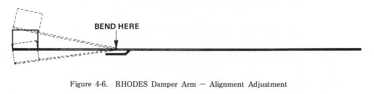
| 4-6 | RHODES Damper Arm - Alignment Adjustment | 4-4 |
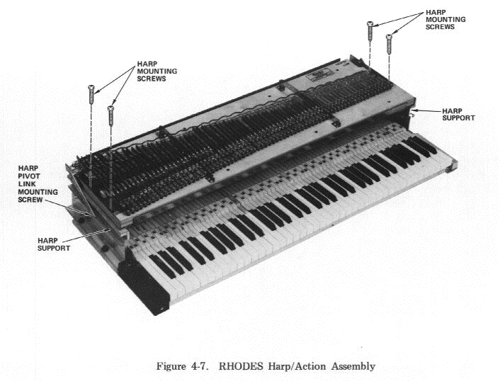
| 4-7 | RHODES Harp/Action Assembly | 4-6 |
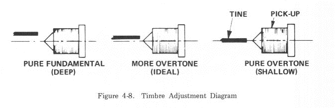
| 4-8 | Timbre Adjustment Diagram | 4-7 |
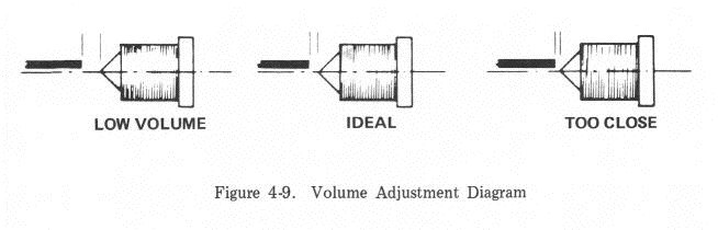
| 4-9 | Volume Adjustment Diagram | 4-7 |
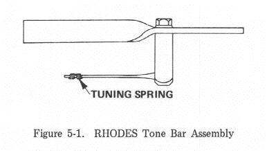
| 5-1 | RHODES Tone Bar Assembly | 5-1 |
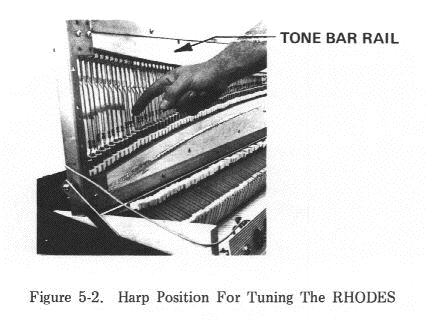
| 5-2 | Harp Position for Tuning the RHODES | 5-2 |
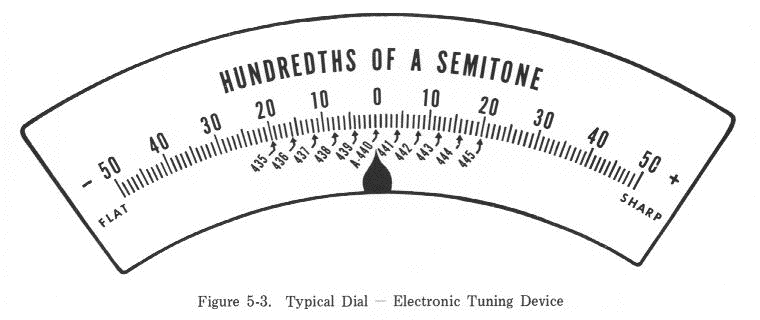
| 5-3 | Typical Dial - Electronic Tuning Device | 5-4 |
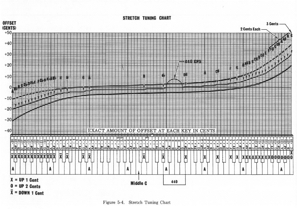
| 5-4 | Stretch Tuning Chart | 5-6 |
| 6-1 | Tone Generator Assembly Removal/Replacement | 6-2 |
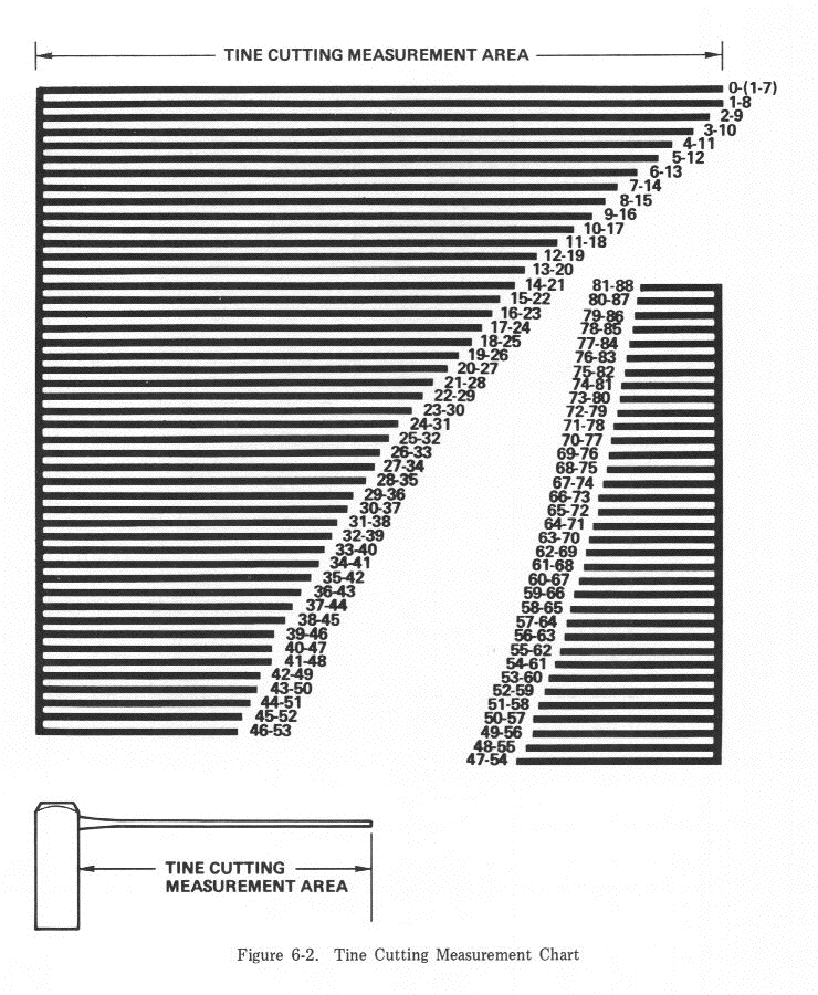
| 6-2 | Tine Cutting Measurement Chart | 6-3 |
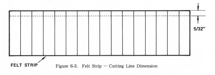
| 6-3 | Felt Strip - Cutting Line Dimension | 6-5 |
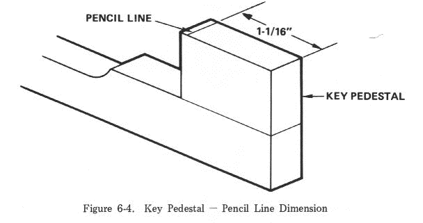
| 6-4 | Key Pedestal - Pencil Line Dimension | 6-6 |
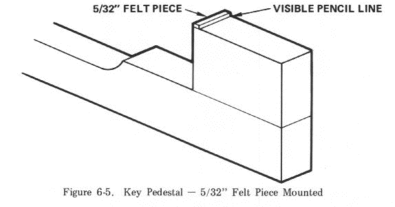
| 6-5 | Key Pedestal - 5/32" Felt Piece Mounted | 6-6 |
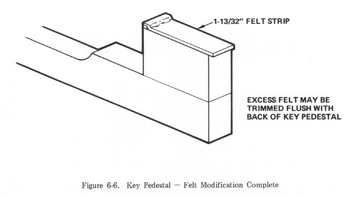
| 6-6 | Key Pedestal - Felt Modification Complete | 6-7 |
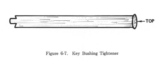
| 6-7 | Key Bushing Tightener | 6-8 |
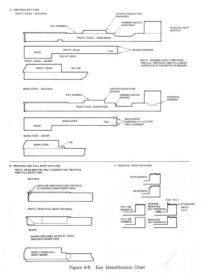
| 6-8 | Key Identification Chart | 6-10 |
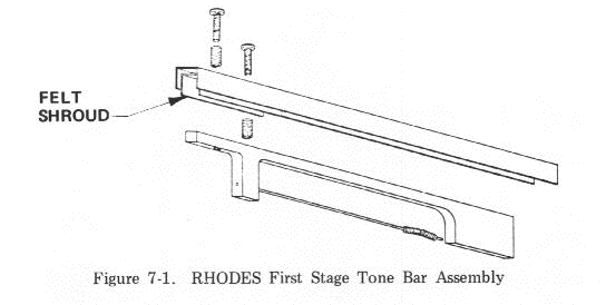
| 7-1 | RHODES First Stage Tone Bar Assembly | 7-1 |
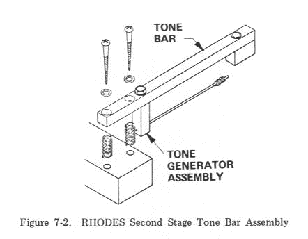
| 7-2 | RHODES Second Stage Tone Bar Assembly | 7-2 |
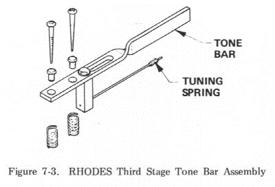
| 7-3 | RHODES Third Stage Tone Bar Assembly | 7-2 |
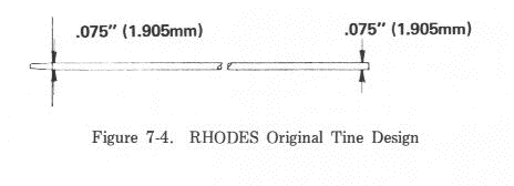
| 7-4 | RHODES Original Tine Design | 7-2 |
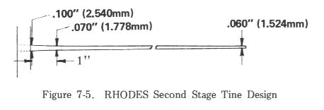
| 7-5 | RHODES Second Stage Tine Design | 7-3 |
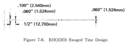
| 7-6 | RHODES Swaged Tine Design | 7-3 |
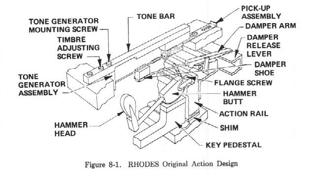
| 8-1 | RHODES Original Action Design | 8-1 |
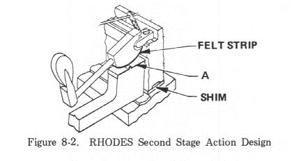
| 8-2 | RHODES Second Stage Action Design | 8-1 |
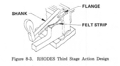
| 8-3 | RHODES Third Stage Action Design | 8-2 |
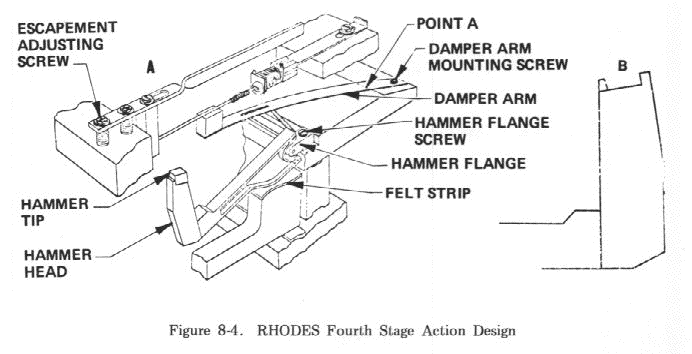
| 8-4 | RHODES Fourth Stage Action Design | 8-2 |
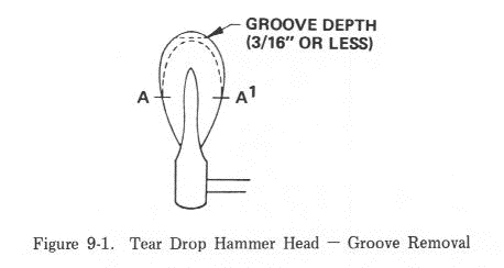
| 9-1 | Tear Drop Hammer Head - Groove Removal | 9-1 |
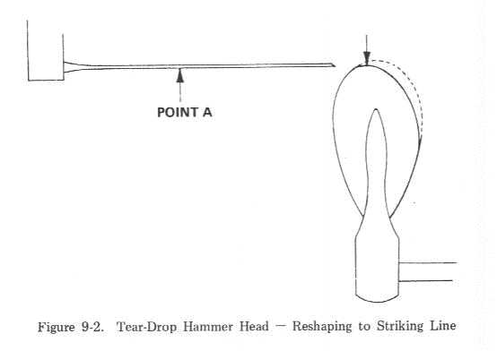
| 9-2 | Tear Drop Hammer Head - Reshaping to Striking Line | 9-1 |
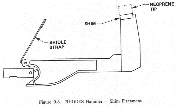
| 9-3 | RHODES Hammer - Shim Placement | 9-3 |
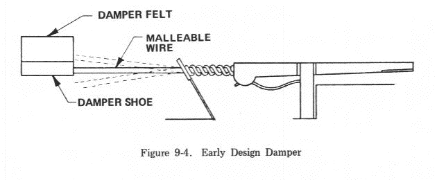
| 9-4 | Early Design Damper | 9-3 |
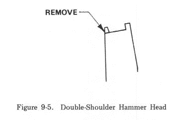
| 9-5 | Double-Shoulder Hammer Head | 9-4 |
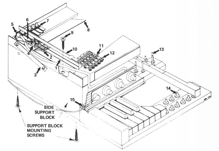
| 9-6 | RHODES Early Design Harp/Action Assembly - Cut-Away View | 9-5 |
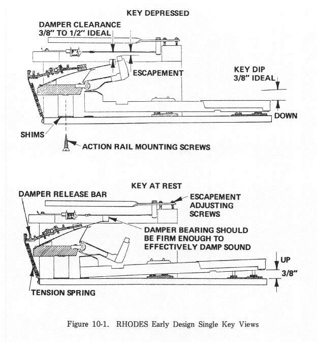
| 10-1 | RHODES Early Design Single Key View | 10-1 |
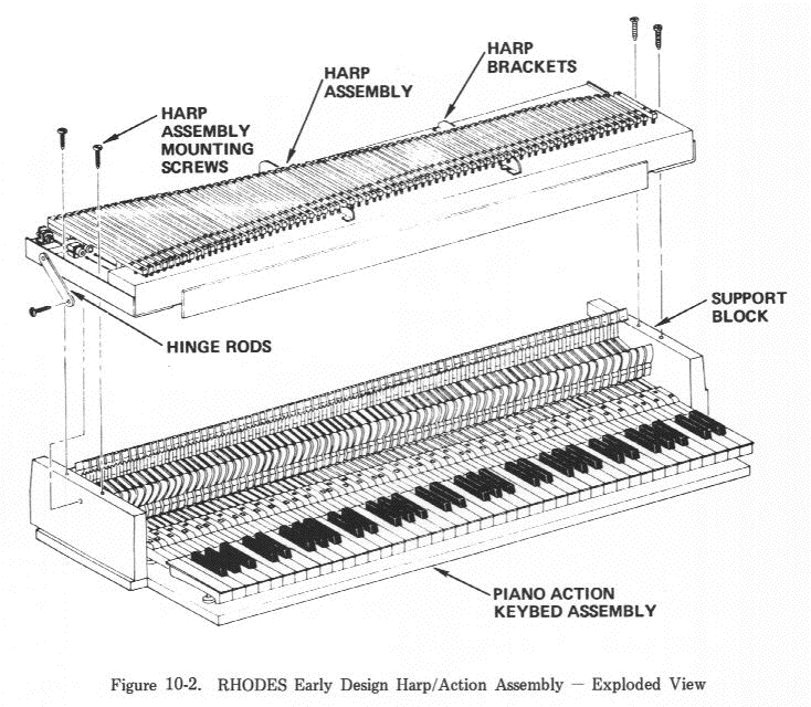
| 10-2 | RHODES Early Design Harp/Action Assembly - Exploded View | 10-3 |
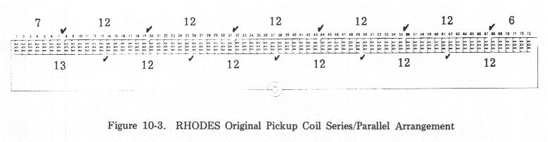
| 10-3 | RHODES Original Pickup Coil Series/Parallel Arrangement | 10-4 |
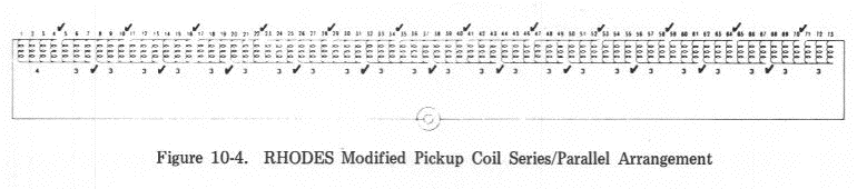
| 10-4 | RHODES Modified Pickup Coil Series/Parallel Arrangement | 10-4 |
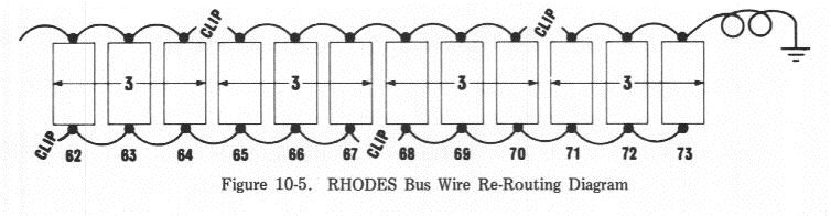
| 10-5 | RHODES Bus Wire Re-Routing Diagram | 10-4 |
| 11-1 | Schematic - Preamplifier Assembly - 100 Watt Suitcase and Janus I | 11-2 |
| 11-2 | Printed Circuit Board - Preamplifier Assembly - 100 Watt Suitcase and Janus I | 11-3/11-4 |
| 11-3 | Schematic - Dual 50 Watt Power Amplifier - 100 Watt Suitcase and Janus I | 11-5 |
| 11-4 | Schematic - Power Amplifier - Janus I | 11-6 |
| 11-5 | Printed Circuit Board - +/-15 Volt Regulator - 100 Watt Suitcase and Janus I Power Amplifier | 11-7/11-8 |
| 11-6 | Printed Circuit Board - 50 Watt Power Amplifier - Suitcase Piano | 11-9/11-10 |
| 11-7 | Printed Circuit Board - 50 Watt Power Amplifier - Janus I | 11-11/11-12 |
| 11-8 | Schematic - Preamplifier - 80 Watt Suitcase and Super Satellite | 11-13 |
| 11-9 | Schematic - Power Module - 80 Watt Suitcase | 11-14 |
| 11-10 | Schematic - Power Supply Regulator Assembly (Peterson Design) -80 Watt Suitcase | 11-15 |
| 11-11 | Circuit Board Assembly - Power Supply Regulator (Peterson Design) -80 Watt Suitcase | 11-16 |
| 11-12 | Schematic - Power Amplifier, Master and Slave - Super Satellite | 11-17 |
| 11-13 | Schematic - Power Control Panel, Master - Super Satellite | 11-18 |
| 11-14 | Schematic - Power Control Panel, Slave - Super Satellite | 11-19 |
| 11-15 | Schematic-Converter Kit I | 11-20 |
| 11-16 | Schematic - Converter Kit II | 11-21 |
| 11-17 | Schematic - Preamplifier and Power Amplifier (Jordan Design) -Suitcase Piano (Pre 1969) | 11-22 |
| 11-18 | Connection Diagram - All Printed Circuit Boards - Instructor Console | 11-23 |
| 11-19 | Schematic - Preamplifier and Power Amplifier - Student Piano (First Version - 1968) | 11-24 |
| 11-20 | Schematic - Preamplifier and Power Amplifier - Instructor Piano (First Version - 1968) | 11-25 |
| 11-21 | Wiring Diagram - Instructor Console | 11-26 |
| 11-22 | Schematic - Master Circuit Board - Instructor Console | 11-27 |
| 11-23 | Schematic - Power Supply - Instructor Console | 11-28 |
Appreciation is due to all who have been involved in producing this manual. Specifically, to our Sales Force, the Retail and Service dealers and the artists who offered suggestions. Last, but by no means least, to our own highly qualified Product Development, Production, Service and Marketing personnel whose many hours of labor and years of expertise have produced what we believe to be a comprehensive aid to servicing and understanding the RHODES Piano.
RHODES Keyboard Instruments U.S.A.
Since its inception in 1965, the RHODES Piano has remained relatively constant in terms of design concept. However, there have been changes in the methods of achieving those design concepts.
Those concepts which have remained constant throughout the history of the RHODES are:
This Manual has a two-fold purpose; one, as a maintenance and repair guide; and two, as a detailed description of the various vintage models together with instructions for upgrading and modernizing the various models wherever possible.