INSTRUCTIONS FOR DISASSEMBLY
Access to the specific areas for needed adjustments or repair is easily accomplished by following the procedures outlined here.
- Harp Cover Removal
The Cover is formed of A. B. S. material and is practically impervious to damage. To remove, lift up on the two back corners of the molded top. With this done, simply pull the front edge free.
- Nameboard Assembly Removal
Disconnect Harp Cable from Harp Jack. With a #2 Phillips Screwdriver, loosen and remove the four (4) screws which mount the Nameboard to the Cheekblocks (two (2) of which are found behind the Nameboard on each end). After removing screws, lift Nameboard Assembly up and away.
- Harp Assembly Removal
The Harp Assembly (Figure 3-1) consists of three major assemblies. The Harp Frame, the Tone Bar Rail and the Pickup Rail.
The Tone Bar Rail and the Pickup Rail are seated into the Harp Frame and secured by fourteen (14) Mounting Screws. Two metal Harp Brackets are then mounted to join the two.
The Harp Assembly is secured to the two aluminum Harp Supports by four (4) Screws (two (2) on each end) as well as the Harp Pivot Links located on each end. Complete removal of the Harp, then, is accomplished by removing the four Mounting Screws as well as the two Screws which secure the Harp Pivot Links.
- Damper Release Bar Removal
The Damper Release Bar (Figure 2-3, 12) is secured to the aluminum Harp Supports by two removable Pivot Pins (Figure 2-3, 11).
- Loosen one Screw (Figure 2-3, 13) on either end of the Damper Release Bar.
- With a small flat-blade screwdriver, slide the Pivot Pin out from the Damper Release Bar through the Nylon Bushing (Figure 2-3, 10) in the Harp Support (Figure 2-3, 9).
- Slide the entire Damper Release Bar loose from the Bushing in the other Harp Support.
Removal of the Damper Release Bar is required in order to reach the Damper Modules for adjustment or removal.
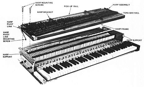
Figure 3-1. RHODES Harp/Action Assembly - Exploded View
- Damper Module Removal
- Remove Damper Module Mounting Screws.
- Carefully push down on each Damper Arm with one hand and gently pull Bridle Strap forward with the other hand so as to slide Bridle Strap away from the formed tongue in the Damper Arm without causing damage to the tongue.
- Pull Damper Module out of detent lip in Action Rail.
- Hammer Removal
It is not necessary to unscrew or displace any of the supporting structures to remove a Hammer. Hold the Hammer Head with the thumb and index finger then rotate either left or right while at the same time twisting on the vertical axis until the protruding ear (pin) pops out of the Hammer Flange. Then, simply lift out, exercising care to ease the Bridle Strap off the Damper Arm Tongue.
- Removal of Keyboard Assembly from Cabinet
CAUTION
This procedure should be accomplished with the Nameboard
Assembly mounted to prevent the Keys from falling out.
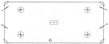
Figure 3-2. RHODES Stage Piano - Bottom View
Stage Piano
- Position the Piano so that the Keys are pointing up with the bottom surface of the Cabinet facing you (Figure 3-2).
CAUTION
Before proceeding with Step b., support the Keybed with one
hand to prevent the Keybed from falling out when the
Mounting Screws are removed.
- Using a #2 Phillips Screwdriver, remove the two Screws (Figure 3-2, 1) which secure the Cabinet to the Cheekblock cleat on the Keybed.
- Remove the two large Screws (Figure 3-2, 2) which mount the Keybed to the Cabinet.
- Place Piano on its bottom surface and remove Keyboard Assembly by lifting out of Cabinet.
Suitcase Piano
- Proceed as with a Stage Piano, again observing the CAUTION on the previous page, following Steps a, b, and c. In addition, since the bottom surface on the Suitcase Piano is of a thinner plywood than the Stage Piano, the four Glides (Figure 3-3, 1) must be removed as well. Proceed with Step d.
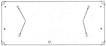
Figure 3-3. RHODES Suitcase Piano Top - Bottom View
- Action Rail and Harp Support Removal
NOTE
The Action Rail is securely locked to both Harp Supports by
means of the Harp Support-To-Action Rail Mounting Screws.
While these Screws can easily be removed, it is suggested that
the two Harp Supports and the Action Rail be maintained as
a 3-piece Assembly.
- Place the Keyboard on its bottom surface as in a playing position.
- Remove the Captive-Washer Nuts that secure the Harp Supports to the Keybed.
- Exercising care not to lose the T-Nuts from the under side, remove the Action Rail Mounting Screws.
- Grasp the Action Rail with both hands and lift off the three-piece assembly.
- Harp Support Removal
- Disassemble Piano as outlined through 7. b.
- Remove the Harp Support-To-Action Rail Mounting Screws.
- Lift Harp Support up and away from Action Rail.
- Cheekblock Removal
This operation is accomplished by removing both the front and rear Cheekblock Mounting Screws.
- Key Removal
After removing the Nameboard Assembly, simply lift up on the front of the Key to free it from the front and center Guide Pins, then pull the Key out from under the Hammer.
TOC - 1 - 2 - 3 - 4 - 5 - 6 - 7 - 8 - 9 - 10 - 11