I N D E X
SECTION PAGE
KEYBOARD . . . . . . . . . . . . . . 1.0 . . . . . . . . . . . . . . . . . . 2
ACTION . . . . . . . . . . . . . . . 2.0 . . . . . . . . . . . . . . . . . . 4
TONE BAR . . . . . . . . . . . . . . 3.0 . . . . . . . . . . . . . . . . . . 7
AMPLIFIER . . . . . . . . . . . . . 4.0 . . . . . . . . . . . . . . . . . . 9
CASE . . . . . . . . . . . . . . . . 5.0 . . . . . . . . . . . . . . . . . .14
STAND . . . . . . . . . . . . . . . 6.0 . . . . . . . . . . . . . . . . . .14
PARTS LIST . . . . . . . . . . . . . 7.0 . . . . . . . . . . . . . . . . . .15
SECTION 1.0 -- KEYBOARD
The keyboard consists of the base-frame assembly and the key assemblies.
The base-frame assembly consists of a BASE FRAME or WOODEN CHASSIS;
mounted transversely across its center is a strip of hardwood called the
BALANCE RAIL; mounted vertically on the balance rail are 38 chromeplated,
brass CENTER rail GUIDE PINS; mounted transversely across the front of the
base frame are 38 FRONT rail GUIDE PINS.
The key assembly consists of 23 assorted WHITE KEYS and 15 BLACK KEYS.
Mounted on the 15 black keys are the black plastic sharps. These may be
reglued with such binding agents as "Miracle" cement obtainable at any 5 &
10 Cent Store, or any plastic aircraft type cement.
The white keys are capped with strips of pyralin "ivory", a product of
DuPont, and standard equipment in piano repair shops.
Each key is slotted and each slot is capped with a FELT BUTTON. These
buttons are slotted to allow a not too snug fit of key to guide pin.
REMOVING KEYS:
All keys may be removed simply by lifting the key off the guide pins.
By grasping the key at the center rail guide pin this can be accomplished
most easily. The amplifier must first be removed to remove keys under it.
To do this do not touch the wiring. Merely remove the three nuts attach-
ing the amplifier to the base-mounting studs with a suitable socket wrench.
Then lift the amplifier off the studs and rest it on the tone-bar. Now all
keys are clear. In replacing the amplifier, be sure to replace the ground
clip.
KEYBOARD TROUBLE SHOOTING:
1.) Sticking Keys
Keys may fail to return to their rest position due to
three basic causes:
a.) Interference with one another;
b.) Tight felt buttons (rare);
c.) Sloping front guide pin, binding inside clearance
hole.
Since the third cause is the most common and easiest
to correct proceed as follows:
(1) Tap the front guide pin lightly backward (away
from the player). Key need not be removed!
(2) If this does not correct the trouble, view down
each side of the key to see if interference with ad-
joining key causes trouble. If so remove key and
file off interference point.
(3) If felt buttons are too tight file, scrape or
simply press apart inside surfaces of felt aperture.
Scraping out inside of key aperture will also help in
freeing keys.
2.) Loose Keys
Keys may be excessively loose due to:
a.) Wear in the key buttons (Part 239-17)
b.) Absence of key button
c.) Short guide pins.
Corrections
Buttons may be tightened by applying aircraft dope
to felt and squeezing aperture as the dope hardens.
If the button is excessively deformed it may readily
be replaced by prying loose and glueing (with any quick-
setting commercial glue) a new button in place. Care
must be taken to position the new button in such a manner
as to retain proper key spacing and movement.
If the guide pins are short, they may be extended by
driving them up from underneath with light hammer blows.
Excessive extension is undesirable since the key should
not contact the guide pin top when depressed.
3.) SATISFACTORY KEY OPERATION may best be checked by raising
the hammers off the keys with the hand. The key should
then be free enough to return to its rest position, but
should not be so loose as to permit adjoining keys to
slap together under light side pressure.
SECTION 2.0 -- ACTION
The action assembly consists of two cast aluminum TONE BAR
SUPPORTS; a laminated maple wood strip called an ACTION BAR to which
is mounted 38 HAMMERS and 30 aluminum DAMPER STRIPS. Also mounted
transversely across the tops of the damper strips and operated by
the foot pedal is a strip of hardwood called a DAMPER RELEASE BAR.
The damper release bar is mounted to the two tone bar supports by
means of two damper bar pivot screws. (Part No. 1119)
Considered as a sub-assembly of the above is the HAMMER DAMPER
ASSEMBLY consisting of the following parts:
a.) Felt hammer head
b.) Hammer shank
c.) Hammer heel
d.) Butt flange
e.) Bridal strap
f.) Aluminum damper strip
g.) Damper felt
When hammers must be replaced, always replace the entire hammer
damper assembly.
ACTION TROUBLE SHOOTING:
1.) Hammers Stick
Hammer may fail to operate due to:
a.) Tight bearing in butt-flange
b.) Interference between hammers
c.) Wedging between tone reeds
d.) Wedging against tonebar
CORRECTIONS
a.) For tight bearings: remove hammer and damper assembly
as follows: Unscrew damper strip, remove damper
release bar, unscrew butt-flange and lift out
hammer damper assembly. Now exercise hammer by
moving up and down under tension on the pin-
bearing. Hammer should move freely under its own
weight. If exercise will not free hammer, install
a new hammer-damper assembly.
b.) Interference between hammers may be corrected by
loosening butt-flange and rotating as required.
If rotation does not suffice, replace offending
hammer and damper assembly.
c.) Hammers wedging between tone-reeds are either due
to twisted hammer, (correct as in b.) above) or
due to improperly located tone-bar. This latter is
simply corrected by moving tone-bar laterally, mak-
ing sure that all hammers strike tone reeds properly.
d.) Hammers wedged against tone-bar are also corrected
by moving tone-bar, in this case forward just enough
to free hammer.
2.) Hammers Miss Tone-Reed
Hammers wedging between tone-reeds are either due to
twisted hammer, or due to improperly located tone-bar. The
latter is simply corrected by moving tonebar laterally, making
sure that all hammers strike tone-reeds properly.
3.) Hammer Creates Rapping Noise:
May be due to loose bearing, (replace hammer as described
above) or may be due to split hammer or broken glue joint.
Replace split hammer, repair or replace broken glue joint.
4.) Dampers Do Not Operate Properly:
When properly adjusted the dampers should deaden all sounds
immediately upon the release of the keys by the fingers. If tone
vibration lingers after the fingers have been released, it is an
indication that the damper felt is not wedged tightly enough
against the reed. This is corrected by bending the front tip of
the aluminum damper strip slightly upward.
In a properly adjusted instrument, with the keys in a de-
pressed position, all dampers should release completely and all
struck tones should be free to vibrate for their full natural
duration. In the event that one or more of the vibrations dies
out too soon after the initial strike, it is an indication that
the damper is NOT releasing. In this event bend the front tip of
the aluminum damper strip slightly downward.
Great care should be used in bending the strips, so as not
to destroy their spring action. Should this occur, release the
strip mounting screw, straighten the strip, replace and reset.
PEDAL ACTION:
Pedal action is controlled by the length of the pedal rod
(Part No. 1124). Proper pedal rod installation is described in the
installation instructions. Tne correct length is determined by in-
serting the rod through the hole in the piano base until it contacts
the damper release bar. Now the lower end of the wooden rod should be
flush with the top surface of the pedal heel. If this is not the case,
adjust the rod to suit by turning the machine screw in or out.
More recent model pianos have two holes in the piano base for
interchangeability between the chrome stands and the wooden stands.
Adjustment and operation for both is similar.
NOISY PEDAL:
Noisy pedal operation may be due to a loose bearing (see Section
6.0), improper rod length (permitting slack) or due to the pedal strik-
ing the floor. The simplest correction for the latter consists of in-
serting felt strips into the pedal housing in such a way as to restrict
the pedal travel to prevent contacting the floor.
SECTION 3.0 -- TONE BAR (Part No. 239-13)
The tonebar assembly consists of 38 tuned tone-reeds pressed into
the cast iron tone bar and of the amplifier pick up bar rubber-mounted
between tone bar web and tone-reeds.
TONE BAR TROUBLE SHOOTING:
1.) Tone-reeds cannot change their pitch unless they are damaged.
Consequently a tone bar once properly tuned will always be
properly tuned. However, occasionally a reed may require re-
placing, may be damaged, or the owner may wish to alter the
basic chromatic scale. Therefore:
To change the pitch of a tone-reed
a.) Shorten the reed with a file to raise the pitch;
b.) File a notch approximately 1/3" from the free end
transversely across the top to lower the pitch.
2.) Do not bend the tone-reeds since this will shorten their life.
Excessive bending, violent shocks, etc. will cause tone-reeds
to break off.
3.) A tone-reed may be replaced by removing the tone bar, driving
the shank of the reed out of the casting, inserting a new reed,
aligning the flat face of the reed shank at right angles to
its former position, (to assure a tight fit) and hammering into
place. The reed must then be tuned. Reeds are identified as
Part No. 239-13-1 to 38, -1 being the lowest note, and -38 the
highest.
It is recommended not to replace tone-reeds unless you are
thoroughly familiar with the operation, but rather to exchange
the entire tone bar at the factory.
4.) ADJUSTMENTS TO THE TONE BAR
The tone bar has been locked to the support bracket by wooden
dowels, to prevent displacement during shipping. These dowels
are necessary only when the piano is to be moved frequently from
place to place. They also provide a rapid method of reposition-
ing the tone bar, if it has been removed for any reason.
In the event that a tone bar is to be replaced, the new tone bar
will normally not fit the dowel holes already provided in the
support. If the dowels are desired (for portability) new holes
may be drilled AFTER properly positioning tone bar. (Recommend
using 3/16 dia. hardwood dowel, #12 drill through tone bar and
bracket). In some instances the dowels themselves restrict, to
a slight degree, the full tone of one or more notes. For maximum
"ring" of all notes it may, therefore, be desirable to remove
the dowels.
The mounting of the tone bar is extremely critical to the tone
quality of the instrument. When making any adjustments observe
the following precautions:
a.) TREBLE hammers must strike the tone-reeds as near
to the throat, (tone bar flange) as possible without
wedging. To permit accurate positioning, the tone bar
has been slotted. (See Sec. 2.1)
b.) For proper resonance, the mounting bolts attaching
the tone bar to the supports may not be drawn up too
tightly. The tone bar must be firm but not clamped
between the rubber grommets. Tighten bolts while play-
ing instrument to determine proper bolt tension.
c.) Check all hammers to determine proper lateral position
of tone bar. (See Sec. 2.2)
d.) Check all dampers for proper operation. (See Sec. 2.4)
5.) Installing a new tone bar:
Observe all precautions enumerated above. Be sure to mount tone
bar between rubber washers. Be sure to adjust dampers as required.
Amplifier lead must be tightly connected to the pick-up bar, and
the shielding grounded by a spring clip to the tone bar.
Occasionally a new tone bar may result in reeds vibrating against
the damper release bar. In this case shave off damper release bar
as required and/or bend spikes away from release bar (only if
necessary).
6.) The Pick-up Bar can be the source of many electronic troubles.
The plastic screws by which it is mounted determine the volume,
(screwed in--low volume, out--high volume). Excessive tightening
will cause hammer "shock" noises, and may break the screws. We
recommend not adjusting the pick-up bar unless fully qualified.
In the event of trouble we suggest exchanging the tone bar assembly.
SECTION 4.0 -- AMPLIFIER (Part No. WE3A)
1.) The amplifier assembly consists of four parts: amplifier, speaker,
tone pickup bar and output jack. The amplifier is a straight,
cascaded resistance capacitance coupled audio amplifier, working
single-ended into speaker. There are three tubes consisting of
one rectifier tube 6 x 5 to supply DC voltages from the AC line.
One dual triode, triodes cascaded to supply voltage gain necessary
to drive 6V6 beam output power tube. Circuit is entirely conven-
tional except for electrostatic pickup bar polarizing voltage and
degenerative feedback which is incorporated on all tubes by leav-
ing cathode resistors unbypassed to reduce harmonic distortion.
Operation of amplifier is as follows: a polarizing voltage is
applied to tone pickup bar mounted on underside of plate, close
to reeds, through an 18 megohm resistor. The changing capacity
in the pickup bar reed combination occasioned by vibrating the
reeds in playing, causes electrons to pile up and recede at
juncture of 18 megohm resistor and pickup bar reed. This vary-
ing voltage is applied through .01 capacitor to grid of 7F7 where
it controls current flow in first section of 7F7. The voltage
which is occasioned by the piling up of electrons on the 18 megohm
resistor is so small that it is further amplified in similar manner
in that second 7F7 section--where it then drives the 6V6 output
tube to give loud speaker volume. The closer the pickup bar is
set to reeds the louder will be the tones; however, resultant
shock noises and slow motion movements of the reed limit gain,
which may be accomplished by this means. A satisfactory adjust-
ment of the spacing is of necessity that one which is most plea-
sant to the ear and which affords the same volume on all tones.
2.) For lowest HUM LEVEL the AC plug, (the wall plug attached to
your Pre*Piano) must enter the wall socket one way only. Try
both possible positions and ascertain which gives you the lowest
hum level.
3.) ADDITIONAL AMPLIFICATION (through your radio-phonograph, separate
amplifier, etc.)
Your Pre*Piano has a socket on the underside of the case on
the aft right hand side of the instrument. A shielded separate
cord is available to plug into this socket in order to connect the
Pre*Piano to any type of outside amplifier or radio-phonograph
combination.
Depending on the application (radio-phonograph, separate
amplifier or public address system) this cord may require special
plugs, and for this reason it is considered an accessory.
The standard 6ft shielded cord will carry part No. 239-11-1.
Any special application may be prepared by your dealer, radio
technician, or write to the factory.
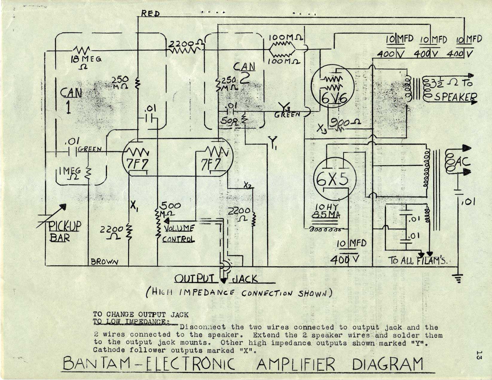
On the drawing supplied, some points have been marked "x"
or "y". The output jack connection "Y" is circled. As it is im-
possible to make a connection which is suitable for all re-ampli-
fication requirements, one has been chosen which seems to us to be
the most likely to be satisfactory. Other points however have
been marked on the drawing which might be more suitable in some
applications. All "y" connections would be for high impedance
outputs. Those marked "x" could be used for a cathode follower.
4.) Amplifier Troubleshooting:
Many amplifier troubles can be repaired by a layman, some
require a technician. When troubles occur it is important to
localize correctly the source between the three separate units:
a.) Amplifier
b.) Loudspeaker
c.) Tone bar assembly
Unless experienced personnel is available, we recommend exchanging
any of the above three units which prove to be faulty, except that
the tubes of the amplifier should of course be replaced separately
if they are at fault.
Distortion in the tone quality such as loud, resonant tones,
sounds similar to mechanical rattles, fuzzy echos after striking
tones, muffled hammer clunks are practically all due to maladjust-
ment of the pickup bar which should be separated from the plate
upon which it is mounted by pure rubber grommets and under suffi-
cient tension to hold all parts firmly. Too much pressure causes
hammer clunking and too little pressure causes rattles due to
pickup bar vibration. The pickup should be held in place by
plastic screws threaded into pickup bar.
Resonances, however, which are identified by notes louder
than others in bass section, may be due to breakdown of speaker
cone; rattles also similar to pickup bar vibration may be caused
by speaker cone breakdown. To check for speaker cone breakdown
hold cone of speaker firmly with hand while striking tones. If
rattle is eliminated, speaker change is advised.
Mechanical rattles of loose parts, or screens in the piano,
or rattle due to 7F7 touching plate or having loose elements in
tube, may occur. Correction: tighten loose parts or replace
7F7. 7F7 rattles are usually identifiable and are described
previously as fuzzy echo after striking tones. Thumping 7F7 tube
will duplicate sound you are looking for, if this is the cause.
Some amplifiers have 6N7 tubes in place of 7F7's. They are
similar type tubes and directions for 7F7's also apply to 6N7's.
A sizzling sound varying from that of frying bacon to the
slow tick of an electric clock, is due to leakage in pickup bar,
or pickup bar lead, or components in can #1. To isolate trouble,
remove pickup leads from pickup, turn amplifier full on. If
sizzling or ticking is still present, a radio technician is re-
quired to repair amplifier. If it does not persist, sound is
due to poor insulation of pickup bar. Rubber grommets should
be of pure grade rubber as supplied by us. Leakage may be due to
dirt or to screw of main pickup connection being too close to
metal. Careful installation should correct trouble. NOTE: Due
to high gain required, some frying or sizzling can always be
detected. This however is at a minimum when the instrument is
shipped. It goes up and down with the volume control and should
not be objectionable when instrument is played.
Hum may be picked up from other electrical equipment such
as fluorescent lights, signs, etc, or may be due to breakdown
of amplifier. To minimize pickup hum, check screen in bottom
of the piano to make sure it is grounded by bolt which passes
through base of screen and has brass clip above amplifier bear-
ing on amplifier chassis. Be sure bolt goes through screen
and that clip touches amplifier chassis. Be sure tone bar is
grounded by foil tape to tone bar supports over rubber mounting
grommets. If correction of these possible sources of trouble
does not correct hum, disconnect tone bar from amplifier. If
hum still persists, trouble is in amplifier and radio technician
is required.
Acoustic feedback is a sound which grows in loudness after
a tone or chord has been struck. Violent rattle of the piano
top may follow. This may be corrected by the layman by making
certain that the following clearances are observed: top should
not touch pickup cover cap or power transformer in amplifier.
Volume control chassis should be free in hole. 7F7 tube should
not touch tone bar. Amplifier chassis should be loose, be
rubber mounted and should not touch piano pins. Pickup bar should
not set too close to spikes. Resonances previously discussed
should also be corrected as they cause acoustic feedback. Feed-
back, though rare, may be due to faulty amplifier or loose
elements in 7F7. If all of the above precautions have not
eliminated feedback, try a new 7F7. If this fails, get a radio
technician.
Low-Pitched vibrations of Treble Notes which decrease in
pitch with the notes, are caused by hammers striking reeds too
far out. Correction is to move plate as far towards speaker as
possible when locking in place. Also adjust pickup bar for
lower volume at extreme treble end.
These low tones are also increased in volume by too much
tension on plate mounting bolts. Rubber washers under plate to
some extent minimize the trouble. On plates having rubber
mountings, some control of the tone quality can be exercised
by tensioning the plate mounting screws. The results can be
attained by playing the full keyboard, one note at a time,
checking all notes by ear and adjusting tightness for a suit-
able balance. Locking treble end down tight will deaden
extreme treble notes; locking bass end down will deaden middle
treble notes. A considerable degree of freedom for the plate is
required to get optimum results. Experimentation with the above
suggestions should very rapidly make the layman quite skillful
in bringing out the best quality of tone in the instrument.
BANTAM ELECTRONIC AMPLIFIER DIAGRAM